This post is a followup from a previous discussion about loads and forces on the catamaran’s crossbeam titled Mast-iculations.
From: Jason
To: Ted Clements
Ted
Thanks for the quick reply. Please help me out, further; what is, “initial righting moment for the vessel?”– the point of no return for a capsize?
And you stated, “it has become operationally generally heavier” in your e-mail. What is “it?” And, when you state “heavier” are you referring to the overall weight of the rig because it was big-sized by Seldén?
Once again we are pushing the envelope. We are about 45 days into cyclone season and should be well north or south of here. Within the next 10 days, given a good weather window, we will sail for about a week to Australia. The land of plenty, where the economy is still hot and prices exceed those of Paris, London, and New York.
I look forward to your reply.
Jason, Antares s/v YOLO
From: Ted
To: Jason
Jason,
Peculiarly, the righting moment for all boats at 0 degrees of heel is always itself 0; until some force acts to push the boat over to some degree, there is no righting moment effort required to recover equilibrium. My careless use of the term ‘initial’ is therefore not correct but as we are dealing with catamarans, the greatest righting moment occurs at sufficiently low angles of heel that the calculation may be simplistically thought of as per the example diagram below. (Also, the ‘moment’ has no time element so the term itself is misleading.) The righting moment is thus approximated at an imaginary few degrees of heel and used to approximate the worst case loading for the mast and rigging.

Antares 44 Calculations – Mast Load Diagram
In fact, the centre of buoyancy will shift (to the left in the diagram) as the cat heels (counter-clockwise) and that will improve the moment arm length but the centre of gravity will also shift left to some degree so more involved calculations are needed to determine the actual maximum heeling angle at which the best righting moment is achieved, probably approximately the point when the windward hull fairbody parts company with the sea.
The restoring or righting moment is the product of the vessel weight multiplied by the horizontal distance between the centre of gravity and the leeward hull centre of buoyancy so the value is thus greater when the vessel is heavier.
In the absence of heeling forces (eg. wind, wave, inertia), the catamaran will want to recover from heeled angles right up to the point when the centre of gravity passes over the centre of buoyancy which can’t shift any further in order to compensate. This may occur when the boat is close to vertical, one hull almost directly above the other; that condition would represent the point of no return. The righting moment which is trying to flop it back down right way up has been diminishing however as the heel angle has been increasing toward that point of no return.
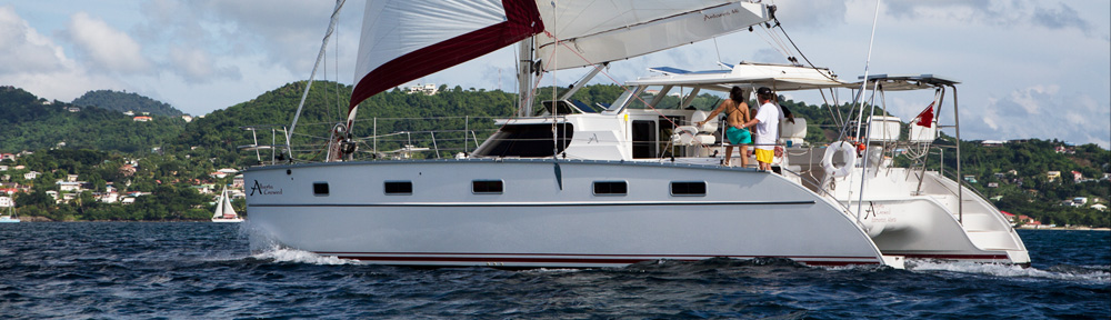
The catamaran may well heel past the angle at which its highest righting moment occurs and still recover as the wind may spill due to the inclination of the sailplan or some action by the crew may relieve the heeling force. Intentionally sailing in the balance is desirable in a racing cat as flying the windward hull greatly reduces drag. The crew however has to maintain constant vigilance to cope with variable conditions of wind and wave and the likelihood of capsize is endemic with this exercise. Most cruising cats are of such a weight in proportion to their sailplans that they are unlikely to fly a hull even if you wanted them to (you don’t).
Racing multihulls demonstrate capsize behaviour rather spectacularly and you may observe that the action is never purely transverse but rather semi-pitchpole.
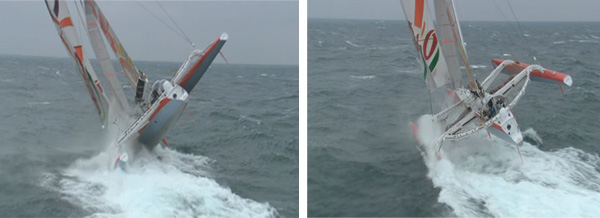
The point of no return? …. not quite.
This kind of capsize mechanism makes our transverse righting moment estimate even more speculative as the real world maximum righting moment would relate to some kitty corner heeling angle. This diagonal moment would be presumably greater than a purely transverse moment due to the increased distance between the centre of gravity and a centre of buoyance which is shifted well forward. (Don’t try this at home.)
To envision the forces at work, imagine trying to tip over a concrete patio slab; the initial lift of one edge is a great strain but it gets easier to hold it up as the vertical is approached and finally you can balance it with one finger.
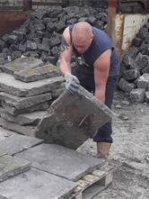
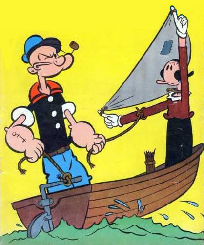
Pictorial assist for the unimaginative
If you now put an umbrella post in the middle of the imaginary slab and tug on that as lever, you will have modelled yourself as wind pressure and it will be apparent that a taller sailplan means a longer lever arm hence greater heeling moments. A wider patio slab is analogous to a wider catamaran hull spacing. If your umbrella post is provided with stays, it will be apparent that they are in tension (pull) and the force within the post is compression (push). The fact that the patio slab is not afloat makes this a simplistic exercise but it is OK for envisioning the catamaran heeling and righting forces. (If you want to envision a more realistic capsize situation, tip the patio slab up on one corner.)
This analogy is not so applicable for monohulls however which typically have relatively low righting moments at shallow angles of heel that increase as the vessel is heeled. This is due to hull form and the effects of ballast keels if they are present. The hull form may be designed such that the centre of buoyancy shifts significantly outboard as the heel angle increases. As long as the centre of buoyance moves over to a greater extent than the centre of gravity, the boat will recover. The analogy of a rocking chair may help with the visualization here.
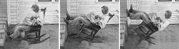
Studying the un-ballasted monohull … low > high > no righting moment progression
Purely form related stability is typical of powerboats and ships which usually have centres of gravity well above the centre of buoyancy. Unless they are very broad of beam, most monohull sailboats have to additionally rely on a ballast keel which lowers the vessel centre of gravity to the extent that it is below the centre of buoyancy to 90 degree heel angle.
Calculating the angle of heel at which a monohull vessel has its greatest tendency to remain upright is quite involved. A rig designer needs to know the peak value of that righting moment and the angle at which it occurs and relate that to the wind pressure that will be exerted by the heeled sailplan. This peak mast design load condition does not usually occur at low angles of heel (the boat will heel and spill the wind) so the simplistic righting moment estimate method used for the catamaran won’t work for the monohull rig designer.
So, the sailing catamaran relies on a very high low angle righting moment to withstand the effect of a vertical, relatively non-yielding sailplan. The sailing monohull relies on a righting moment that may peak closer to 90 degrees heel (an amalgam of effects due to hull form and keel weight) but needs only withstand the effects of a wind spilling sailplan.
Typically the catamaran rig loads, which are proportional to these righting moments, are approximately 50% greater than those of a monohull vessel of the same length. Seldén or any other mast manufacturer takes this into account when engineering the rig, hence they want to know the catamaran’s righting moment approximation which is a function of the vessel weight. The rig weight itself will be a function of materials and technologies used, which for a cruising vessel ought to be from the ‘more practical’ end of the spectrum in my opinion. Weight aloft is of less concern to catamarans as the effects of a higher centre of gravity are not so dire at low operational angles of heel. A monohull is relatively more sensitive to weight aloft as the rig is normally significantly heeled and a burden to the recovery effort.
Weight may be positive to the catamaran stability but it is not so desirable from a performance point of view as it increases the draft and wetted surface which causes drag as well as making the boat less able to react to light wind shifts and wave conditions.
I have been contemplating a way to address the specific catamaran structural shortcomings described in your first letter. The nature of these boats is such that they will inevitably be subject to flexing; this means that some toughness is preferable to rigid strength, (rubber tire as opposed to plain steel wheel). Rigidity in some areas adjacent to those more flexible may result in stress concentrations and failures in the connective components. Ideally stresses in the structure experienced in a seaway are evenly countered and dissipated in a structure stiff enough to support the necessities of function (the mast doesn’t loll from side to side). Figuring out the exact forces and loads experienced at every point and the exact properties of the shapes and materials used to resist them is an exercise of sufficient magnitude and uncertainty in such a complex structure as a cruising sailing catamaran that we are compelled to rely largely on empirical knowledge. Even when fancy engineering studies are applied to specific components, the results are still subject to; ‘Does this look strong enough to you?’
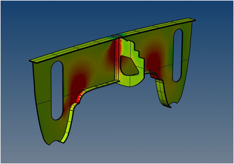
A simplistic example of finite element analysis engineering applied to the Antares catamaran mast bulkhead structure reveals the zones of higher loading due to mast compression
In the quest for efficient structures (light weight), the racing design philosophy may even be applied; ‘If it doesn’t break it’s too heavily built’. Obviously such an approach is not applicable to the cruising sailboat but a totally problem free structure (as the Antares 44 catamaran prototype proved to be) does cause the design types involved to murmur amongst themselves, ‘Is it over-built?’
Fibreglass construction permits the efficient employment of compound curved shapes, e.g. like an egg. This advantage of form may not be taken advantage of as effectively as it can be if vestigial design sensibilities pertinent to sheet material construction (wood, metal) have carried over into the fiberglass boat design. This is often observed as ‘flats’ used when naturally stiff compound curved form may have been better structurally. Large radius tapering connections between inherently stiff structures are also possible with fiberglass which spreads loads and flexibility organically.
Aside from the design/engineering aspect of things, there is some variability in the construction process and materials used. This may result in well-engineered structures being compromised because the intended process wasn’t carried out. Maybe this is what the damaged cats in question have succumbed to?
Endurance at sea is the historic proving ground for marine structures and no builder can get a good night’s sleep until his boats have some kind of positive track record. In this sense, a proven design certainly trumps the latest in design fashion.
guh guh guh guh guh!
Regards,
Ted
