QUESTION:
I often see 30″ listed as the minimum required underwing clearance for comfortable blue water sailing. Why? Is more clearance better? Given that clearance is based on DWL and that actual clearance is dependent on actual waterline with a given load (and usually somewhat less than the DWL clearance) how much of a problem is heading for blue water with a heavily laden cat?
ANSWER:
A simple (I hope) analogy for bridgedeck clearance is set out in “Vessel Stability” already on the site.
In summary, the wider the distance between the catamaran hulls the greater will be its inclination to stay on the level. Considerations such as; seeing the corners, will limit the practical over all beam of the vessel however. Also, in cruising catamarans the hulls are tied together with an accommodation deck suspended above the waves. This bridge deck influences the practical spacing distance of the hulls as it should be kept high enough to clear almost all wave action. In order to do that, it must get higher as the space gets wider.
The actual number of 30″ may be adequate for a 44′ vessel with moderate hull spacing but inadequate for a vessel of very wide stance or larger overall dimension. As the bridgedeck clearance influences all the other design parameters for the vessel, most obviously the heights of the accommodations on the bridgedeck, you may be suspicious of any cat that looks rather too sportscar’ish. Look underneath and see what sacrifice to seaworthiness has been made.
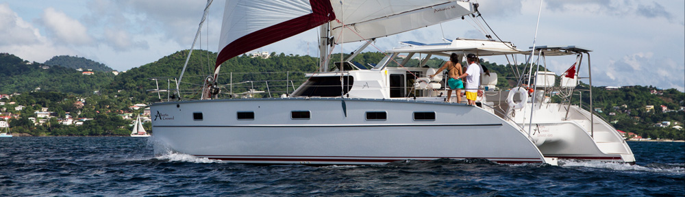
You can watch this video of the Antares 44i shot during a sea trial.
When cat designers, builders and current owners walk the boat shows they have no trouble spotting the potential slammers, once your sensibilities are educated to the possibilities you are probably sufficiently armed.
Here is a link to an article by Sackville Currie published in Blue Water Sailings Multihulls Quarterly suggesting a guideline formula to consider the relative merits of diverse cat designs in regard to bridgedeck clearance. https://www.antarescatamarans.com/pdf/BridgedeckClearance.pdf As he points out, an acceptable clearance depends on what you intend to use the boat for. In light of the impossibility of predicting the exact dynamics of how waves and a variety of hull shape variations will interact, no blanket value will be a perfect indicator but it will provide some idea of what to expect. It does put your vessel in the zone.
I would emphasize the value of his observations in regard to the marketing influences that affect the design as a whole. No parameter can dominate the design process and the exercise is one of compromise and accommodation. How things are resolved will constitute a package that will be pleasing and suitable for some but less than ideal for others. Regardless, it would be a mistake to buy a relatively low bridge deck vessel and take it offshore.
If you are not inclined to run around measuring everyone’s boat, variations that will occur due to loading in any case, just be sure to take a look under any vessel that you propose to own. Check the voyaging record and anecdotal material available for the design if you intend to go offshore.
Take a sea trial in choppy conditions, lie on the tramp with your head over the crossbeam and look aft under the bridgedeck. Its a great experience just before you loose it to seasickness.
It will make you feel better when you observe that a lot of noise is generated by waves slapping around. This racket is unavoidable to some degree. It’s the structure shuddering solid water slam that is to be avoided. If you got your hair wet in the above exercise, you have probably exceeded the design’s comfortable wave tolerance.
A bridgedeck related discussion I generated for a powerboat design addresses some of the clearance implications for the rest of the vessel. Although the speed regimes are different for power catamarans, those that operate in the displacement or sem-displacement mode have similar criteria for bridgedeck considerations.
The parameter; keep the bridgedeck as high as is practical and as organic in shape as can be accomplished.
The desirable height is proportional to the catamarans beam as measured from hull center lines. The wider the spacing, the higher the bridgedeck needs to be to pass over waves and chop of a given height. Even if it is extraordinarily high, the water will contact it eventually as the roughness and vessel speed increase. We don’t want it too high.
Much of the interior floor is placed on the upper surface of the bridgedeck and this in turn dictates the floor height in the hulls themselves which we like to constrain to about 30″ lower. The hull floor height and subsequent headroom dictate the minimum sheer line height; so indirectly, the bridgedeck clearance controls the sheer line and hence has a very significant effect on the vessels aesthetics.
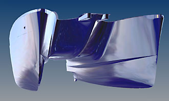 A bow-like cutwater divides any waves that may reach so high. The shape also has inherent strength and ideal load dissipation characteristics
Conceding a practical minimum clearance appropriate to our hull spacing, we then are obliged to minimize the effects of any water impacts that may slap against the large bridgedeck surface. As a first line of defense, we created some tapering splash rail ledges on the inboard hull surfaces. They have multiple functions; deflecting some wave action from striking the bridgedeck, increasing the interior accommodation volume, decreasing the bridgedeck structural span, and stiffening the inboard hull structure.
The underside of the foredeck is a large step up from the bridgedeck surface but it also forms part of the underbody when wave action is considered. If the simplest of shape transitions were employed, a broad barge front would be created. We could do better by creating a bow-like cutwater to divide any waves that may reach so high and also structurally support the foredeck in way of the anchor rollers. It remained to marry these forms together with some generous corner fillets and almost eliminate the flat surfaces. This shape has inherent strength and load dissipation characteristics ideal for our purposes.
The parameter; don’t let the wake between the hulls contact the bridgedeck.
In this particular vessel, the overall beam was limited to 18′ for practical operational reasons. The outboard hull surfaces were carried down as vertically as possible to keep the hull centres of buoyancy as widely spaced as possible. (This precluded outboard splash rails moulded within the hull surfaces, as the effective width requirement would have been deducted from the submerged hull center spacing.)
In addition to maximizing stability, the widest possible hull spacing was sought in order to help alleviate a common catamaran wake phenomenon. The two inboard bow waves converge at a fixed distance aft of the bow, proportional to the cutwater spacing, (the waves vee angle is a constant). This means that if the tunnel between the hulls is long and narrow, the convergent wave with its double amplitude height, could rise high enough to contact the aft and of the bridgedeck in some conditions if not constantly.
Any water contacting the bridgedeck would generate drag, and restriction of the tunnel exit cross section area would inhibit the flow of air, turbulent water and spray through the passage. In addition to drag, turbulent air at the tunnel entrance could carry spray on to the foredeck.
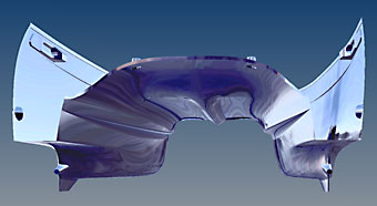 The bridgedeck surface is significantly higher in the aft section below the cockpit floor
The solution to this problem was to lift the bridgedeck surface significantly higher in the aft section below the cockpit floor where the accommodation floor height restriction would not preclude doing so. The remaining challenge was to integrate that curvaceous shape through to the foreward cutwater section of the bridgedeck as smoothly as possible, (thank you Rhino 3D modeling program).
